I have an alpha source of 241Am in the center of a circular disk-shaped packing. The strength of the source is 2.99 µCi. How many alpha particles per second from this source would fall on an alpha probe of rectangular dimensions 7.2 cm by 13.8 cm at 1 cm and 2 cm distance from the source, respectively? If the efficiency of the probe is 15%, how many counts per second should it read?
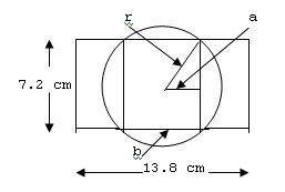
We can make a reasonable estimation of the expected count rate by assuming that the source dimensions are much smaller than the detector dimensions so that it can be treated as a point isotropic source and that there is no significant attenuation of alpha particles in the source material or source covering or detector covering. The predominant alpha particles from 241Am have energies of about 5.5 MeV and have a range in air at 22°C of about 4.34 cm. This range will limit the area of the detector intercepted by the alpha particles and complicates the determination of the fraction of emitted particles intercepted by the detector; we shall refer to this fraction as the geometry factor, G. The geometry factor is also the ratio of the solid angle subtended by the active detector facial area at the point source divided by 4π. The sketch below (not to scale) shows dimensions in the plane of the detector face that we will use to calculate the geometry factor when the source is centered 1 cm above the detector face.

When the source is 1 cm from the detector face, the radius of the circle shown, r, is 4.22 cm, calculated as one leg of a right triangle whose other sides are the 1 cm distance to the source from the detector face and the 4.34 cm oblique line (i.e., the alpha particle range) from the source to the face of the detector, and the line designated “a” has a length of 2.20 cm for this case; line “b” has a length of 4.40 cm. The geometry factor associated with a point source centered at distance D above a circular detector face of radius r is given by
Gcircle = 0.5[1 – cos(tan-1(r/D))] (1),
and for r = 4.22 and D = 1 we obtain Gcircle = 0.385. The geometry factor associated with a point source centered at distance D above a rectangular detector face of width W and length L is given by
Grect = (1/π)tan-1[(W/2D)(L2/(L2 + W2 + 4D2))0.5] (2),
and for W = 4.40 cm, L = 7.2 cm, and D= 1 cm we obtain Grect = 0.341. (See NCRP Report No. 112, Calibration of Survey Instruments Used in Radiation Protection for the Assessment of Ionizing Radiation Fields and Radioactive Contamination, National Council on Radiation Protection and Measurements, pp. 114–115, 1991, for geometry factors.)
In the above figure the portion of the detector that we are interested in is that within the facial area of the detector that is bound on two sides by the circular elements. Thus we must evaluate the geometry factor for the facial area that includes the inner rectangle in the above figure plus the two portions of the circular area that lie within the detector face. The solid angle subtended at the source by a portion of a circular area is proportional to the angle swept out as the radius moves between its limiting points. For each of the circular sections within the detector area this angle can be calculated as 2.044 radians, and for each of the sections outside of the detector facial area the angle is 1.098 radians. The geometry factor associated only with the portions of the circular area outside of the detector area we shall call Gout and that associated with the circular portions inside the detector area we shall call Gin; we shall apply the ratio 1.098/2.044 = 0.537 as a multiplier on Gin to represent Gout. The geometry factor associated with Gin plus Gout is equal to Gcircle – Grect = 0.385 – 0.341 = 0.044. Then
Gin + 0.537Gin = 0.044, Gin = 0.0286, and Gout = 0.0154
The total required geometry factor is then represented by the sum of that for the rectangular element plus the geometry factor for the circular elements within the detector face:
Gtotal = Grect + Gin = 0.341 + 0.029 = 0.370.
The rate, R, at which alpha particles impinge on the detector is then the particle emission rate times Gtotal:
R = (2.99 µCi)(3.7 x 10⁴ Bq µCi-1)(0.370) = 4.09 x 10⁴ s-1.
If we multiply this value by the intrinsic detection efficiency (intrinsic efficiency is the probability that an alpha particle incident on the detector will produce a count), which I am assuming is the 0.15 figure that you quote,* we obtain the expected count rate, C:
C = (4.09 x 10⁴ s-1)(0.15) = 6.14 x 10³ s-1.
If the intrinsic efficiency had its maximum value of 1.0 rather than 0.15, the expected count rate would be the same as R, 4.09 x 10⁴ s-1. For most alpha detectors the window thickness does not generally exceed 2 mg cm-2. Such a window will also restrict the solid angle subtended at the source—e.g., for a low atomic number window of 2 mg cm-2, the geometry factor would be about 0.31 for a point isotropic source sitting directly on the center of the window of the detector. For a detector with no window the geometry factor for a comparable arrangement would be 0.50.
I shall leave the case for the 2 cm distance for you to try. You can use the same general methodology as that employed above; the geometry factor determined should be somewhat less than for the 1 cm case since the solid angle subtended at the source by the active portion of the detector will be smaller than for the 1 cm case.
Good luck.
George Chabot, PhD, CHP
*This figure seems low to me for most typical alpha detectors, such as thin window gas detectors and ZnS scintillators, for which the intrinsic efficiency is often much closer to unity.
Answer posted on 1 November 2007. The information posted on this web page is intended as general reference information only. Specific facts and circumstances may affect the applicability of concepts, materials, and information described herein. The information provided is not a substitute for professional advice and should not be relied upon in the absence of such professional advice. To the best of our knowledge, answers are correct at the time they are posted. Be advised that over time, requirements could change, new data could be made available, and Internet links could change, affecting the correctness of the answers. Answers are the professional opinions of the expert responding to each question; they do not necessarily represent the position of the Health Physics Society.


